
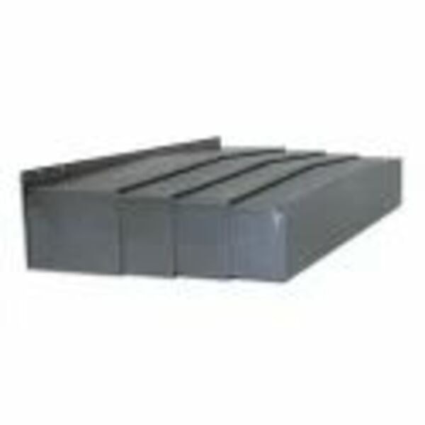
A cover that matches the VMC stroke can still bind, collide with the column, trap coolant or fail to protect the guideway if its collapsed length, mounting faces and travel direction are wrong. By the end, you will know how to measure the machine, prepare the interface, install each section, test the complete stroke and decide whether a telescopic design suits the application.
Key takeaways
- Measure guideway dimensions, stroke, mounting height and clearance before ordering.
- Confirm cover orientation, mounting points and interfaces from the machine layout.
- Align each telescopic section before testing the complete axis stroke.
- Specify local support when access, lifting or alignment exceeds your maintenance team’s capacity.
What to measure before ordering a VMC telescopic cover
Before requesting a quotation or fabrication drawing, record the machine make and model and measure the guideway, not just the axis specification. A VMC telescopic cover must fit the guideway width and height, guideway length, actual axis stroke, mounting height, and required clearance.
With the machine stopped, measure along the travel direction with the telescopic cover fully collapsed and fully extended. Mark whether it opens toward the table, column, or operator side, and record available space at both ends of travel. Note every interference point involving the spindle head, table, enclosure, lubrication lines, and guarding.
- Fully closed and fully extended cover lengths
- Number of sections and section pitch
- Maximum speed and acceleration
- Mounting-hole pattern, including hole spacing, diameter, and access
- Mounting-face geometry and any required adaptor space
Do not order from nominal X, Y, or Z stroke alone. Compare the dimensions this way:
| Dimension | What it describes | Why it matters |
|---|---|---|
| Nominal axis stroke | Control-programmed travel | Does not define the cover envelope |
| Actual axis stroke | Measured machine movement | Sets the required extension |
| Closed cover length | Collapsed cover footprint | Prevents collision at travel ends |
| Extended cover length | Maximum cover footprint | Confirms guideway protection and clearance |
| End space | Clear distance beyond each travel limit | Prevents impact with the column, table, or enclosure |
How to identify orientation, mounting and interface requirements
A physically matching cover can still bind when installed backward. For telescopic cover installation, stand at the drawing’s defined reference side, identify left-hand or right-hand arrangement, then confirm travel direction and mark which attachment is fixed and which moves.
State whether mounting is horizontal or vertical, and whether sections open toward the table, column or operator side. Reversing this orientation can put the scraper, drain or section overlap into the coolant and chip path.
Do not force a VMC machine cover in Pune into an out-of-line guideway; correct the machine or use an adaptor bracket.
Your installation drawing checklist must show:
- Mounting brackets, base plates and locating surfaces
- Fastener size, quantity and tool access
- Gaskets, seals, scrapers and wipers
- Drain orientation and low-point outlets
- Permitted drilling or tapping points
- Whether the casting accepts new holes or needs an adaptor bracket
| Protection type | Best fit | Wrong choice when |
|---|---|---|
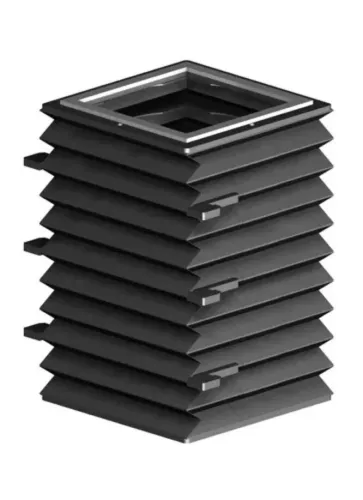
| Telescopic steel cover | Compact folding protection and high chip resistance | Flexible access or very tight bends dominate |
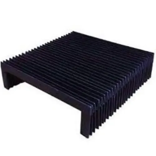
| Bellows cover | Flexible access around changing geometry | Hot, sharp chips can attack fabric |
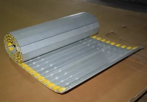
| Rollway cover | High chip resistance with rolling movement | The envelope requires compact section stacking |
| Partial chip guard | Limited shielding at a local exposure | Guides need sealed protection from coolant and dust |
How to prepare the VMC before removing the old cover
1. Shut down the VMC and isolate electrical energy with lockout/tagout. Close the pneumatic supply, bleed stored air, and release hydraulic or spring energy where applicable. Open the enclosure only after the axis has stopped and the control shows no active movement.
2. Create safe access through the enclosure before starting telescopic cover installation. Remove guards that obstruct the work, then remove the old cover without dragging chips across the guideway. Label every fixed and moving attachment, and photograph the original orientation, overlap and drain direction.
3. Clean the guideway, mounting faces and surrounding enclosure. Remove trapped chips, coolant pooling and abrasive sludge, then inspect for damaged wipers, blocked drains, bent brackets, misaligned faces and protruding fasteners. Correct each defect before placing the replacement cover.
4. Confirm that lubrication lines, sensors, cable carriers and enclosure panels stay outside the cover envelope throughout travel. Do not force the cover to correct an out-of-line guideway, table, column or bracket; that transfers side loads into the sections and causes binding.
5. Correct chip and coolant flow before commissioning. A high-pressure jet aimed at a joint, wiper or drain opening can defeat an otherwise suitable cover. Keep maintenance access for wiper replacement, guideway inspection and chip removal; routine service should not require dismantling the table, spindle head or enclosure.
How to install and align the telescopic sections
A VMC telescopic cover must be aligned before its fasteners are fully tightened; forcing it into place creates side loads, binding and uneven section overlap.
1. Clean the guideway, brackets and locating faces. Remove chips, coolant residue and burrs, then verify that the guideway, table, column and mounting surfaces are aligned. Do not use the cover to correct a machine-axis or bracket alignment problem.
2. Place the first, fixed section against its bracket or base plate. Install the specified fasteners finger-tight, leaving enough movement for adjustment.
3. Attach the moving end to the table, column or machine slide. Keep the fixed and moving attachment points as shown on the installation drawing; never lock both ends as fixed attachments.
4. Set the cover axis parallel to the guideway and square to the mounting face. Adjust brackets or add shims instead of pulling the cover sideways with fasteners.
5. Move the table or cover slowly by hand where safe, or use low-speed jog mode, through the complete stroke. Confirm that the sections telescope in the intended order, retain the specified overlap at full extension, collapse without side rubbing and do not strike during reversal.
6. Tighten the fasteners in sequence to the drawing torque. Then install the final scraper, wiper, gasket and drain arrangements. This completes the telescopic cover installation.
How to commission the cover across the complete machine stroke
Commissioning succeeds only when the VMC telescopic cover runs through the complete machine stroke, not when it looks correct in one parked position. A static inspection will not reveal impact at reversal, hesitation, side loading or chip entry.
1. Run the cover through the full stroke in low-speed jog mode. Listen for section impact, rattling and scraping, and watch for unequal extension, skewing, hesitation, seal distortion or lost overlap.
2. Repeat the cycle at progressively higher operating speeds and acceleration. Check motor load or drive alarms when available; a sudden increase indicates side loading or trapped debris.
3. Inspect the cover after dry cycling. Then repeat the test with the actual coolant delivery and chip direction. Confirm that drains stay open, coolant does not pool, and chips do not collect in a low pocket.
4. Check each wiper for continuous contact without excessive compression. A distorted lip increases resistance and wears quickly; a loose or damaged lip admits chips.
5. Recheck clearances at both ends and at intermediate positions, including enclosure doors, spindle-head travel, lubrication points and cable routing. Correct every contact before release.
The cover protects guideways and moving machine elements, not people. Keep enclosure doors, interlocks and the machine safeguards required by the risk assessment fully operational.
When to specify local installation support in Pune
Specify local installation support when the cover must match a machine’s measured interface, not just its stroke or steel grade.
Ask a Pune supplier for:
- Machine make and model; photographs of both travel ends; a marked-up envelope drawing; guideway and mounting dimensions; stroke; closed and extended lengths; section count; mounting orientation; speed and acceleration.
- Coolant pressure and direction; chip material; temperature exposure; wiper needs; drain requirements; and any restriction on drilling or tapping.
- The installation drawing, overlap dimensions, fastener schedule, locating-surface requirements, maintenance access and commissioning checks.
A VMC telescopic cover for installation in Pune needs this operating detail because flood coolant, high-pressure jets, aluminium chips, cast-iron dust and hot chips change the wiper, seal and drainage design.
| Proposal comparison | What to check | Why it matters |
|---|---|---|
| Generic quotation | Quoted length and steel grade | It can miss collapsed-length clearance or mounting conflicts |
| Measured interface review | Envelope, attachments, overlap and operating conditions | It exposes collisions before fabrication |
| Local installation support | Site access, drilling limits and commissioning checks | It reduces rework during fitting |
When comparing a VMC machine cover in Pune, consider Kalavijay Engineering if its team will review the envelope, mounting arrangement and operating conditions before fabrication. Change the design when the machine layout, coolant system, stroke or chip pattern changes.
Related products
 | Telescopic Cover Telescopic Cover For VMC Machine Telescopic covers will protect your Ball Screw from Metalic chips, Dust etc........... View product → |
 | Telescopic Cover BFW VMC Machine Telescopic Cover Wherever guideways on machines have to be protected, we have a suitable solution. View product → |
Frequently asked questions
What should you measure before ordering a VMC telescopic cover?
Record the machine make and model, guideway width and height, guideway length, actual axis stroke, mounting height and required clearance.
How do you identify VMC telescopic cover orientation and mounting requirements?
Check the machine layout and existing cover for travel direction, fixed and moving ends, mounting faces, bolt patterns, wipers and clearance around adjacent components.
How should you prepare a VMC before removing its old cover?
Isolate power, secure the moving axis, remove chips and coolant, document the existing mounting arrangement, and provide safe access for removal and lifting.
How do you commission a telescopic cover after installation?
Move the axis slowly through its full stroke, check section overlap, mounting security, wiper contact, noise, binding and interference before returning to production.
When should you specify local installation support in Pune?
Request local support when the cover is large or heavy, access is restricted, the mounting interface is uncertain, or alignment cannot be verified safely by your team.
Related products
 | Telescopic Cover We are a leading manufacturer of CNC Machines Telescopic Cover. The offered product is manufactured using optimum quality raw materials. View product → |
 | Telescopic Cover Wherever guideways on machines have to be protected, we have a suitable solution. View product → |