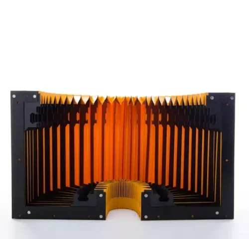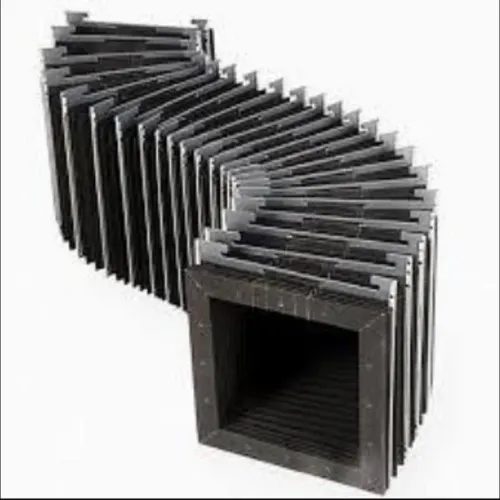

A rail length alone cannot produce a workable bellow cover: the supplier needs the guide-block envelope, actual stroke, folded-space limit, motion direction, mounting geometry, and contamination conditions. By the end, you will have a measurement and acceptance checklist for ordering a custom cover that clears the carriage, tracks correctly, and survives the machine’s real operating environment.
Key takeaways
- Record rail length, carriage dimensions, travel, and end clearances.
- Measure the installed machine at both ends of carriage travel.
- Calculate folds from stroke, compression, extension, and available space.
- Approve mounting details and a first article before production.
Start with the rail, carriage, and travel data
Provide the rail, carriage, and travel data before asking for an LM rail bellow cover quotation; rail length alone cannot establish the custom bellow cover size.
1. Record the rail manufacturer and model, rail width and height, carriage manufacturer and model, carriage length, width, height, and any projecting lubrication fittings or seals.
2. State the usable carriage stroke, not just the rail’s overall length. Identify the fixed mounting location and the mounting face that moves with the carriage, then give the required cover length fully extended and fully compressed.
3. Measure the available cover envelope: maximum height and width, rail centerline, fold pitch, and clearance to adjacent rails, ballscrews, cable carriers, chip conveyors, guards, and machine surfaces. Include the minimum bend radius if the cover must turn or offset.
4. Send the mounting-hole pattern for both ends, including hole diameter, pitch, edge distances, thread type, and the direction of the mounting plates. A cover that fits the rail but misses the machine’s mounting faces will not install correctly.
5. Mark the carriage at both travel limits and provide photographs or a dimensioned sketch of the installed machine. Show the cover fully compressed and fully extended, including service-access zones; this exposes interference that a mid-travel measurement hides.
Specify whether the cover moves with the carriage or remains fixed across the protected span. Keep guideway wipers and lubrication provisions in the specification: the bellow reduces incoming chips and coolant, but it does not replace either.
Measure an installed machine at both ends of travel
Rail length tells you where protection is needed, not how large the cover must be. Put the carriage at its fully retracted position and measure from the actual fixed mounting face to the moving mounting face. Repeat the measurement with the carriage fully extended.
The difference is the usable stroke; it is not automatically equal to the rail’s overall length.
Record these readings for the custom bellow cover size:
- Rail centerline height and the available cover width above the guide
- Carriage length, width, height, and the position of its mounting face
- Fixed and moving mounting-face locations at both travel limits
- Required extended length and the space available for the folded stack
- Cover height and width, including the maximum outside dimensions
- Fold pitch, approximate fold count, and the minimum bend radius allowed
- Mounting-hole pattern, hole size, thread depth, and plate thickness
- Clearance to guideway seals, lubrication ports, ballscrews, cable carriers, adjacent rails, and chip conveyors
Check the envelope with the carriage fully compressed and fully extended, not at mid-travel. A cover that fits the stroke can still collide when folded, block a service port, or stretch past its mounting face.
For a cover that moves with the carriage, measure the moving interface through its complete travel; a fixed cover instead spans the stationary protected area. Include both positions in the installation drawing, with the rail centerline and service-access zones shown. This is essential when replacing a distorted or stretched old cover.
Calculate folds, stroke, and the complete clearance envelope
Verify the cover at its two limits, not at mid-travel: the extended length must span the usable stroke, while the compressed stack must fit inside the machine’s shortest available space. Treat the bellow cover as a machine rail protection system, not as a sleeve sized to rail length.
For a carriage-mounted cover, calculate the working extension as Lextended minus Lcompressed. That difference must equal the carriage’s usable stroke, with mounting overlap and end-stop allowance shown on the drawing.
Estimate fold count as working extension divided by fold pitch, then confirm the supplier’s actual fold geometry and compressed stack height; a small pitch change can make the stack too long.
Draw the complete clearance envelope in both fully compressed and fully extended positions. Mark the rail centreline, carriage position, mounting faces, maximum cover height and width, and the cover’s minimum bend radius. Include service-access zones and show the envelope at every point of travel, not just at the endpoints.
Check the moving envelope against:
- Guide block edges, lubrication ports, and end seals
- Adjacent rails, ballscrews, cable carriers, and chip conveyors
- Fixed guards, brackets, table edges, and machine doors
- Coolant drainage paths and cleaning access
A cover that clears at full extension can still foul when folded. Confirm that folds do not pinch against the carriage, retain abrasive slurry, or close over a lubrication point. For a replacement, measure the old cover only as a reference; stretching or distortion can hide a nonworking clearance.
Match the construction to heat, chips, coolant, and motion
Choose the fabric from the hottest and dirtiest exposure, not from the ambient temperature inside the enclosure. Record continuous surface temperature and short-duration peak temperature, including radiant heat, hot chips, welding sparks, coolant temperature, and wash-down fluid.
| Construction choice | What to specify | When it applies |
|---|---|---|
| Coated polyester or nylon fabric | Oil- and coolant-resistant coating, sealed seams | Wet machining and ordinary metal chips |
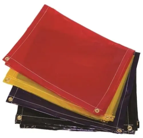
| Heat-resistant fabric with spark protection | Fabric temperature rating, replaceable outer shield | Welding spatter, hot chips, and radiant heat |
| Grinding-duty construction | Abrasion-resistant outer layer, tight fold closure, cleaning access | Fine abrasive dust or slurry |
| Reinforced bellows with guide strips | Slats or strips that prevent sagging and fold collapse | Long travel, vertical mounting, or high-speed motion |
Specify guides when the bellow cover can sag, twist, or contact the carriage. Use reinforced mounting plates and a defined minimum bend radius; a loose fabric sleeve can rub the LM rail, invert a fold, or snag an adjacent part.
Set fold pitch and opening direction for the contamination. Small, closed folds limit chip entry, while outward-opening folds can drain coolant more readily; either design fails if it forms a pocket that retains abrasive slurry. Add drain paths and cleaning access where fluid can collect.
A bellow cover reduces contamination but does not replace carriage wipers, guideway seals, or lubrication. For a Pune machine, name the exposure precisely: dry chips, wet coolant, grinding dust, welding spatter, outdoor dust, or monsoon moisture.
Test the complete lm rail bellow cover through its stroke at speed, checking rubbing, fold inversion, liquid retention, and interference.
Specify the mounting interface and approve the first article
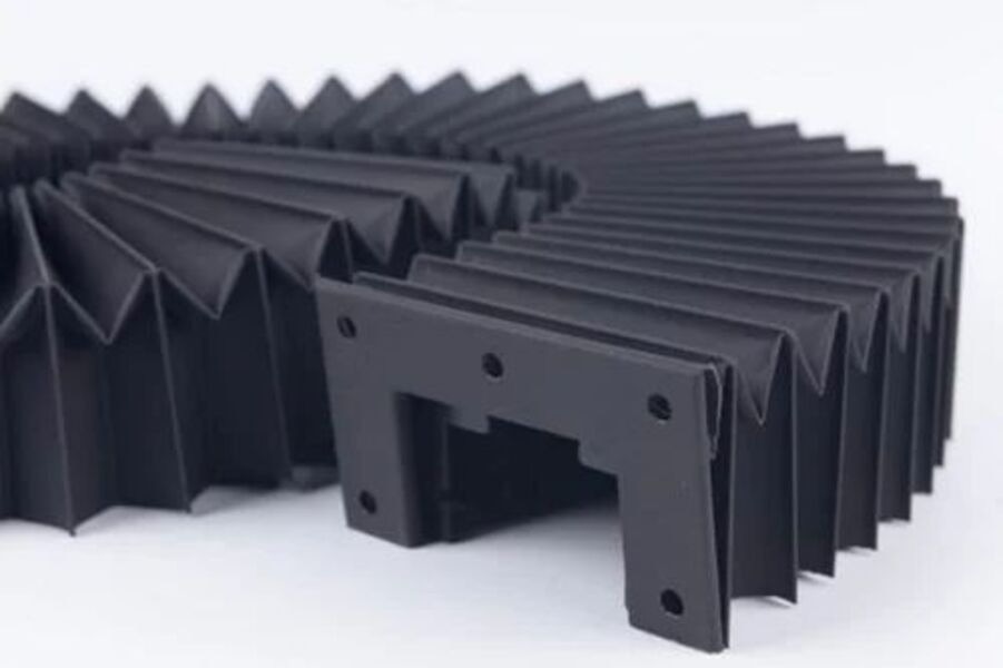
The mounting interface decides whether machine rail protection survives real travel. Show whether the cover moves with the carriage or remains fixed across the protected area, then define the fixed and moving datums, plate thickness, mounting-hole pattern, slot orientation, and the alignment reference used during installation.
Misaligned plates twist the folds and can make a correctly sized cover bind.
Put these details on the purchase drawing:
- Rail make and model, rail width and height, guide-block length, width, and height
- Usable stroke, compressed length, extended length, fold pitch, fold count, and minimum bend radius
- Cover height and width, including the maximum outside envelope at full compression
- Fixed and moving mounting locations, hole diameter, centre distances, thread type, and fastener access
- Clearance to lubrication ports, wipers, adjacent rails, ballscrews, cable carriers, and chip conveyors
- Required alignment datums, allowable mounting-plate deflection, and the machine’s operating speed
Ask the supplier to return a dimensioned approval drawing before production. Kalavijay Engineering can use that drawing to resolve hole positions and clearances rather than guessing from the rail length.
Approve a dimensional first article on the actual machine. Run the carriage through its complete stroke at operating speed, in both compressed and extended positions, with coolant and representative chips where practical. Reject it for rubbing, fold inversion, snagging, liquid retention, plate deflection, or interference; also verify that wipers and lubrication points remain accessible.
Related products
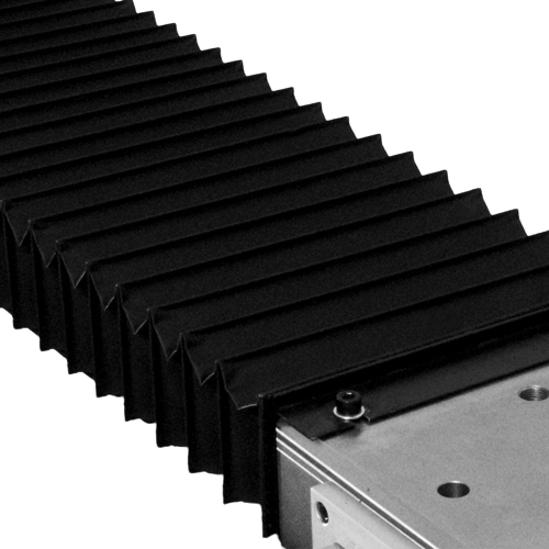 | Bellow Cover We provide LM Rail Bellow Covers to protect your LM Rail from dust, oill and coolant, Spatter etc. View product → |
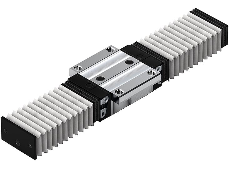 | Bellow Cover We are munufacturer for Custimized LM Rail Bellow Cover. Liner Bearing Bellow Cover If You Want To Protect Your Hiwin, THK, GRI, Linear Bearings And... View product → |
Frequently asked questions
What data do you need to specify an LM rail bellow cover?
Provide rail and carriage dimensions, travel length, speed, mounting points, operating temperature, and exposure to chips, coolant, oil, or sparks.
Why measure an installed machine at both ends of travel?
Measurements at both positions reveal changing gaps, obstructions, compression space, and the complete clearance envelope.
How do you calculate the folds and stroke of a bellow cover?
Use the required travel, compressed length, extended length, fold pitch, and available installation space to establish the fold count and stroke.
How should you choose bellow cover construction?
Match fabric, coatings, reinforcement, wipers, and temperature resistance to heat, chips, coolant, oil, sparks, and motion speed.
What must you approve before manufacturing a custom bellow cover?
Approve the mounting interface, compressed and extended dimensions, clearance envelope, drawings, and first-article inspection criteria.